XBee firmware management with X-CTU

Managing Digi’s XBee radio modules requires using their X-CTU package to upload the correct firmware. In this post we explain how.

This post is slightly depressing: not because it’s on an unhappy topic, but because the effort and software needed to manage XBee radios is so complex to set up. In many ways this is just a function of the good design of the XBee: it’s so minimal in terms of footprint and power consumption at run-time that it offloads a lot of work to external tools (and the user) at system build-time. But it’s still a lot of work to get such a small piece of kit running.

X-CTU is intended to upload firmware to XBee radio modules. This is needed to change the firmware between router and co-ordinator of the Zigbee mesh network, and between the different protocol variants that the XBee radios can support.

Xbee on USB

One limitation of X-CTU is that it only works on Windows: if you’re running Linux, X-CTU will run under Wine. You can download the latest X-CTU from Digi’s X-CTU page; alternatively, there’s a version installed on the Citizen Sensing VM.

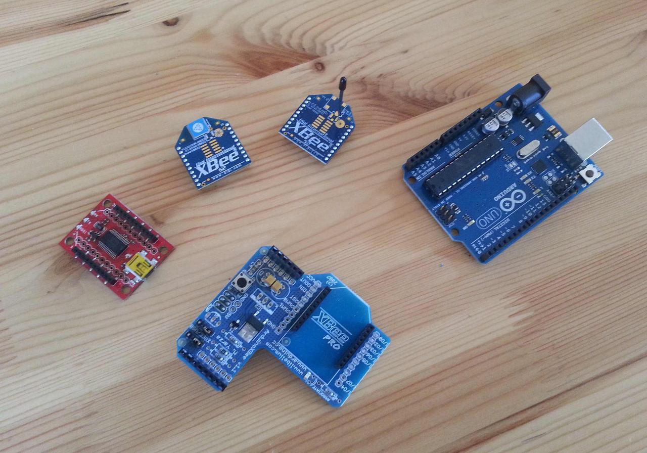
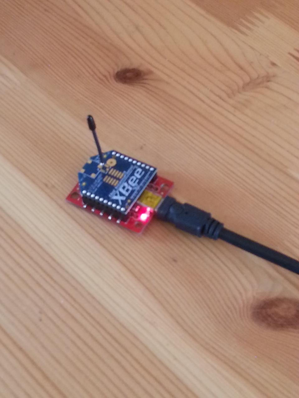
To use X-CTU you need to connect your XBee module to your computer. The easiest way to do this is using an XBee USB breakout board, which provides an XBee socket and a USB socket. Insert the radio into the board, plug in a USB cable, and plug the other end into a USB socket. The light on the breakout board will then come on (see photograph above).

X-CTU in operation

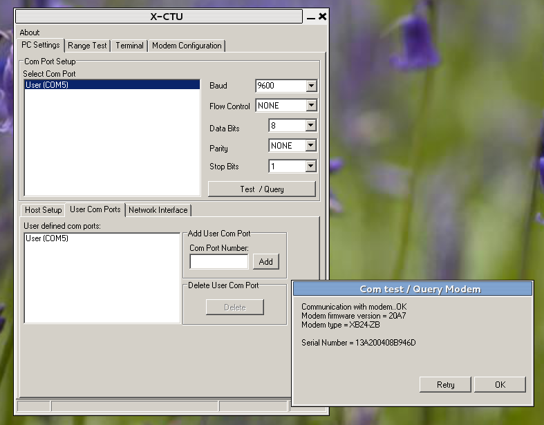
You next need to start up X-CTU and tell it where the XBee is. It hangs off a Windows COM port, and X-CTU will typically find it automatically. You should then be able to press the “Test/Query” button, and X-CTU will interrogate the XBee and display a small window showing some information about it, as shown in the screenshot on the right: the details don’t matter, but this shows that the XBee is talking to the computer properly.

X-CTU router firmware

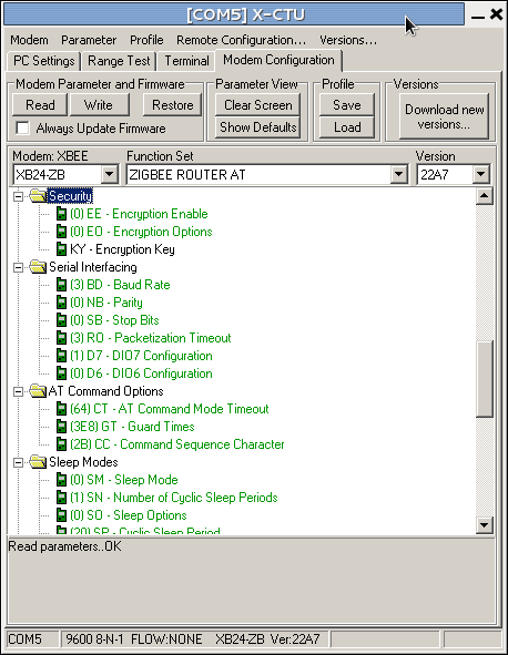
Assuming everything is now working correctly, the next step is to decide what firmware to download to the radio. Click on the “Modem configuration” tab, and then click the “Read” button: this reads the firmware that’s on the XBee at the moment, and puts the details into the window. Typically this results in a display like that shown on the left. The important things to notice are the two drop-down boxes labelled “Function Set” and “Version”. The function set is the description of the firmware, in which case indicating that the XBee is running Zigbee router firmware that responds to AT commands (more on this below).

X-CTU co-ordinator firmware

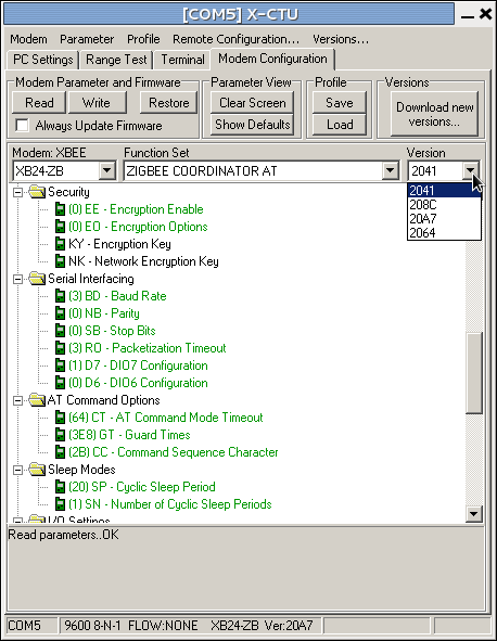
To download a new firmware, we then select the function set and version we want to use. Suppose we want to make this XBee into the mesh co-ordinator. We change the function set to “Zigbee Coordinator AT” (keeping with Zigbee and the AT command set) in  “Function set” the drop-down, then select the most recent version of this function set from the “Version” drop-down. (Versions are identified by hex numbers: the most recent in the screenshot right is “20A7”, that being the highest hex number. Unfortunately X-CTU orders the numbers alphabetically, not in hex-numeric order.) Pressing “Write” will update the radio’s firmware, and the radio is then ready for use as a co-ordinator.

If you look through the list of function sets, there will be quite a few options, including protocols other than Zigbee. These probably aren’t worth too much exploration, but you’ll also notice that there are Zigbee AT and API function sets corresponding to the two modes (transparent and API) that the XBee can support. Be sure to select the correct one for your application.

That’s it: the radio is now ready for use.

Advanced use: setting optional parameters

There’s one more thing that X-CTU can be used for: it can set parameters to the firmware function set, and this is sometimes important when using the radios.

X-CTU parameter setting

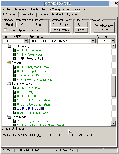
When you’ve read the firmware from a radio, the main part of the X-CTU window contains a hierarchy of folders and cryptic values, for example “(4) PL - Power level”. These are parameters that can be changed to modify the detailed behaviour of the radio. Some can also be set using AT commands. The example we used sets the radio’s power level to 4. If you click on this, it will show a drop-down box giving other options. You might, for some applications, choose to reduce the radio power to 1 (“low”) to save batteries. If you choose this and then write the firmware to the radio, the module will use this power setting.

In the example shown on the left, we’re changing the AP parameter (“API enable”) to 2, which is needed for the xbee-arduino library to work properly. If we now write the firmware (with the Zigbee co-ordinator API function set selected as shown), the radio will be ready for use.

Mesh networking

A mesh network is a way of setting up a communications system when there’s no fixed infrastructure available. They’re often used for communications in remote sites, and on sensor networks.

If you’ve used wifi, you’ve used an infrastructural wireless network in which there is a dedicated router that talks to all the devices in its range (phones, tablets, laptops, wireless-enabled printers, …) and connects them to the internet. The devices don’t talk to each other directly: if they want to exchange information (to print a document, for example) they do via the router.

Another kind of infrastructural network is the cellular telephone service. All calls go through the cell towers: if you call your friend, and she happens to be standing next to you, your phone still talks to the nearest cell tower which then talks to her phone — a round trip that might be a couple of kilometres! While this sounds a bit barmy, it simplifies the design of the network and the software needed to manage it, and is fine in situations where there is plenty of power and room for the infrastructure.

By contrast to these large-scale systems, XBees provide mesh networking in which the devices co-operate to route traffic from the sensor motes (using router radios) to the base station (running a co-ordinator radio). As well as generating and receiving messages, nodes in the network also co-operate in moving other nodes’ traffic. There is no infrastructure — the nodes are both the users and the providers of the network — which means a mesh can be deployed in areas without any “official” network coverage, or to provide functions (like low power) that the infrastructure that is available can’t deliver. Each mesh network works on a particular network protocol, different to the ones used for wifi or cellular telephony.

XBee radios

The XBee is a series of small radio modules that implement the Zigbee protocol and work well with Arduinos.

Xbees and an Arduino

XBees are made by Digi. The range includes a number of options: you almost certainly want some variant of the Zigbee range. The Series 2 (S2) modules seem to offer good performance, low power, and a useful range of functions. There are several different antenna types and two different radio powers (2mW and 50mW): larger power provides more range (1km nominal as opposed to 100m) at the cost of twenty-five times the power consumption: best avoided unless really needed. A collection of XBee modules co-operate to form a mesh network that’s quite robust against partial failure, which makes them great for use in the field.

To get XBees working with an Arduino you need several pieces of hardware and software:

  • Two or more radios (obvious, but surprisingly easy to only buy one…)
  • One or more Arduinos
  • One Arduino XBee shield for each radio-equipped Arduino
  • One XBee USB breakout board
  • The X-CTU firmware management software
There are also variations of Arduinos that take XBee modules directly, as well as other sensor mote systems that can work with them: they’re not completely Arduino-specific.

When buying radios, buy them all the same series: the different series aren’t guaranteed to interwork (although they often do). In the photograph above there are two different XBees: one with a patch antenna and one with a whip antenna.

The Xbee shield fits on top of the Arduino. They’re sold without a radio module.

The breakout board is used to connect an XBee to the USB port of a computer, allowing your network to be accessed from the desktop. This is useful for debugging and for data logging, unless you’re also going to build a dedicated data logger.

The X-CTU software manages the firmware on the radio module. Because the radios are small and low-power, they don’t have room for a sophisticated software stack, and so aren’t programmed in the normal way. Instead you download a firmware providing exactly the functions you need. Each network is given an identifier (a personal area network id or PAN) so that several networks can co-exist in the same area without interfering with each other. Each network has exactly one co-ordinator, with the others being routers, Co-ordinator and router use different firmware: you nominate one of your radios as co-ordinator (which will typically live on the base station, or on the data logger) and use X-CTU to load co-ordinator firmware to it; the other radios get router firmware and are placed onto the sensor motes.

XBees actually have two communication modes you can choose between, by choosing different firmware. The simplest is the AT firmware. These provide simple, text-based communications between radios: what one Arduino writes as text comes out on the other. In this mode the XBee also responds to Hayes AT commands, a standard way of controlling a modem (which is what an XBee technically is): we’ll explore these commands in another post. This function set — router and co-ordinator — sets up what might be called a transparent network, in the sense that it behaves just like a serial pipe. This makes it easy to get things up and running.Text-based interaction isn’t great for computer-to-computer communications, however, not least because of the effort (and memory) needed to understand text-based protocols. For this reason, the XBee also supports API function sets that provide binary communications. These are better for computers, and faster when running, but require more programming and more intellectual effort to understand. We’ll deal with API communications in another post too.

We’ll deal with the details of using X-CTU in another post, as well as explaining how to set up a simple network.

First bit of soldering done

The first proto-shield has been assembled.

The SparkFun prototype shield for the Arduino essentially lets you put a small custom circuit onto an Arduino shield.

Arduino prototyping shield

The “bare” version has a small area for soldering-up in the middle of the shield. I decided to make a slightly more re-usable version with a small breadboard so I could experiment with the electronics without soldering.  The assembly is very easy, although the board is of course very cramped. The “helping hands”  were invaluable.

Several lessons learned: I need a finer bit for my soldering iron, a smaller pair of side-cutters for trimming the wires, and my soldering skills are truly appallingly rusty. The shield has a couple of places where it can take additional headers (for controlling the LEDs and using the spare button that’s not being used for reset, and to bring the ICSP connectors through) which it would be useful to have.

Approaching Zero: The Extraordinary Underworld of Hackers, Phreakers, Virus Writers, and Keyboard Criminals

Paul Mungo (1993)

3/5. Finished Sunday 23 June, 2013.

(Originally published on Goodreads.)