Radio survey

A simple radio survey establishes the ranges that the radios can manage.

The 2mW XBee radios we’ve got have a nominal range of 100m — but that’s in free air, with no obstructions like bushes, ditches, and houses, and not when enclosed in a plastic box to protect them from the elements. There’s a reasonable chance that these obstacles will reduce the real range significantly.

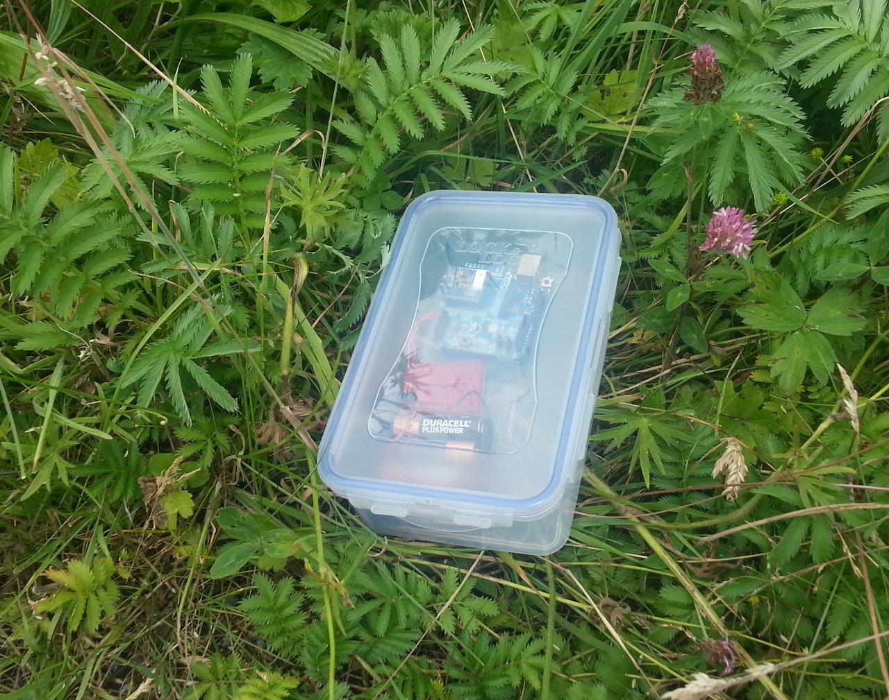
Arduino, radio, batteries, and their enclosure in the field (literally)

A radio survey is fairly simple to accomplish. We load software that talks to a server on the base station — something as simple as possible, like sending a single packet with a count every ten seconds — and keep careful track of the return values coming back from the radio library. We then use the only output device we have — an LED — to indicate the success or failure of each operation, preferably with an indication of why it failed if it did. (Three flashes for unsuccessful transmission, five for no response received, and so forth.) We then walk away from the base station, watching the behaviour of the radio. When it starts to get errors, we’ve reached the edge of the effective range.

With two sensor motes, we can also check wireless mesh networking. If we place the first mote in range of the base station, we should then be able to walk further and have the second mote connect via the first, automatically. That’s the theory, anyway…

(One extra thing to improve robustness: if the radios lose connection or get power-cycled, they can end up on a different radio channel to the co-ordinator. To prevent this, the radio needs to have an ATJV1 command issued to it. The easiest way to do this is at set-up, through the advanced settings in X-CTU.)

The results are fairly unsurprising. In an enclosure, in the field, with a base station inside a house (and so behind double glazing and suchlike) the effective range of the XBees is about 30—40m — somewhat less than half the nominal range, and not really sufficient to reach the chosen science site: another 10—20m would be fine. On the other hand, the XBees mesh together seamlessly: taking a node out of range and placing another between it and the base station connects the network with no effort.

This is somewhat disappointing, but that’s what this project is all about: the practicalities of sensor networking with cheap hardware.

There are several options to improve matters. A higher-powered radio would help: the 50mW XBee has a nominal range of 1km and so would be easily sufficient (and could probably be run at reduced transmission power). A router node halfway between base station and sensors could extend the network, and the cost of an additional non-sensing component. Better antennas on the 2mW radios might help too, especially if they could be placed outside the enclosure.

It’s also worth noting that the radio segment is horrendously hard to debug with only a single LED for signalling. Adding more LEDs might help, but it’s still a very poor debugging interface, even compared to printing status messages to the USB port.

Sleepy sketches

Keeping the microcontroller asleep as much as possible is a key goal for a sensor system, so it makes sense to organise the entire software process around that.

The standard Arduino software model is, well, standard: programs (“sketches”) are structured in terms of a setup() function that runs once when the system restarts and a loop() function that is run repeatedly. This suggests that the system spends its time running, which possibly isn’t all that desirable: a sensor system typically tries to stay in a low-power mode as much as possible. The easiest way to do this is to provide a programming framework that handles the sleeping, and where the active bits of the program are scheduled automatically.

There are at least two ways to do this. The simplest is a library that lets loop() sleep, either directly or indirectly. This is good for simple programs and not so good for more complicated ones, as it means that loop() encapsulates all the program’s logic in a single block. A more modern and compositional approach is to let program fragments request when they want to run somehow, and have a scheduler handle the sleeping, waking up, and execution of those fragments. That lets (for example) one fragment decide at run-time to schedule another

If we adopt this approach,we have to worry about the fact that one fragment might lock-out another. A desktop system might use threads; this is more problematic for a microcontroller, but an alternative is to force all fragments to only execute for a finite amount of time, so that the scheduler always gets control back. This might lead to a fragment not running when it asked (if other fragments were still running), but if we assume that the system spends most of its time asleep anyway, there will be plenty of catch-up time. Doing this results in an actor system where the fragments are actors that are scheduled from an actor queue.

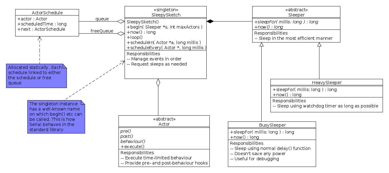
Turning this into code, we get the SleepySketch library: a library for building Arduino sketches that spend most of their time sleeping.

SleepySketch design

There are a few wrinkles that need to be taken care of for running on a resource-constrained system. Firstly, the number of actors available is fixed at start-up (defaulting to 10), so that we can balance RAM usage.(With only 2k to play with, we need to be careful). Secondly, we use a class to manage the sleeping functionality in different ways: a BusySleeper that uses the normal delay() function (a busy loop) with no power-saving functions, a HeavySleeper that uses the watchdog timer to shut the system down as far as possible, and possibly some other intermediate strategies. Actors are provided by sub-classing the Actor class and providing a behaviour. We also allow pre- and post-behaviour actions to define families of actors, for example sensor observers. We separate the code for an actor from its scheduling.

The standard library uses singleton classes quite a lot, so for example the Serial object represents the USB connection from an Arduino to its host computer and is the target for all methods. We use the same approach and define a singleton, Sleepy

The program structure then loops something like this. If we assume that we’ve defined an actor class PingActor, then we can do the following:

void setup() {
   Serial.begin(9600);
   Sleepy.begin(new HeavySleeper());

   Sleepy.scheduleIn(new PingActor("Ping!"), 10000);
}

void loop() {
   Sleepy.loop();
}

The setup() code initialises the serial port and the sleepy sketch using a HeavySleeper, and then schedules an actor to run in 10000ms. The loop() code runs the actors while there are actors remaining to schedule. If the PingActor instance just prints its message, then there will be no further actors to execute and the program will end; alternatively the actor could schedule further actors to be run later, and the sketch will pick them up. The sketch will remain asleep for as long as possible (probably for over 9s between start-up and the first ping), allowing for some fairly significant power saving.

This is a first design, now just about working. It’s still not as easy as it could be, however, and needs some testing to make sure that the power savings do actually materialise.

Understanding Arduino sleep modes: the watchdog timer

The Arduino has several sleep modes that can be used to reduce power consumption. The most useful for sensor networks is probably the one that uses the watchdog timer.

Powering-down the Arduino makes a lot of sense for a sensor network: it saves battery power allowing the system to survive for longer. Deciding when to power the system down is another story, but in this post we’ll concentrate on documenting the mechanics of the process. The details are necessarily messy and low-level. (I’ve been greatly helped in writing this post by the data sheet for the Atmel ATmega328P microcontroller that’s used in the Arduino Uno, as well as by a series of blog posts by Donal Morrissey that also deal with other sleep modes for the Atmel.)

Header files and general information

To use the watchdog timer, a sketch needs to include three header files:
#include <avr/power.h>
#include <avr/wdt.h>

These provide definitions for various functions and variables needed to control the watchdog timer and manage some of the other power functions.

Power modes

A power (or sleep) mode is a setting for the microcontroller that allows it to use less power in exchange of disabling some of its functions. Since a microcontroller is, to all intents and purposes, a small computer on a chip, it has a lot of sub-systems that may not be needed all the time. A power mode lets you shut these unneeded sub-systems down. The result saves power but reduces functionality.

Power modes are pretty coarse control mechanisms, and can shut down more than you intend. If your project is basically software-driven, with the Arduino making all the decisions, then a “deep” power-saving mode is ideal; on the other hand, if you rely on hardware-based signals at all, a “deep” sleep will probably ignore your hardware and the Arduino may never wake up.

The watchdog timer is used to manage the “power-down” mode, the deepest sleep mode with the biggest power savings.

Watchdog timer

The Arduino’s watchdog timer is a countdown timer that’s driven by its own oscillator on the microcontroller. It’s designed to run even when all the other circuitry is powered down, meaning that the microcontroller is drawing as little power as possible without actually being turned off completely.

Why “watchdog” timer? The basic function of a watchdog timer is to “bite” after a certain period, where “biting” means raising an interrupt, re-setting the system, or both. A typical use of a watchdog is to make a system more robust to software failures. Since the watchdog is handled by the microcontroller’s hardware, independent of any program being run, it will still bite even if the software gets stuck in an infinite loop (for example). Some designers set the watchdog ahead of complex operations, so that if the operation fails, the system will reset in a short amount of time and end up back in a known-good configuration. At the end of a successful operation, the program disables the watchdog (before it bites) and carries on. Of course this assumes that the operation completes before the watchdog bites, which means the programmer needs to have a good idea of how long it will take.

Setting the time-out period

It’s as well to understand how watchdog timers on microcontrollers work. Typically they have a fairly coarse resolution, counting a fixed number of timer ticks before “biting” and performing some function. In the case of the Arduino, the watchdog timer is driven by the internal oscillator running at 128KHz and counts off some multiple of ticks before biting. This value — the number of ticks counted — is referred to as the “prescalar” for the timer.

The prescalar is controlled by the values of four bits in the watchdog timer’s control register, WDTCSR. To set them up, you pick the value of prescalar you want and set the appropriate bits. If the bits contain a number ( i ), then the watchdog will bite after ( (2048 << i) / 128000 ) seconds. So ( i = 0) means the watchdog bites after 16ms; ( i = 1 ) produces  delay of 32ms; and so on up to ( i = 9 ) (the largest value allowed) means the watchdog bites after about 8s.

The word “about” is important here: the oscillator’s exact frequency depends on the supply voltage to the chip and some other factors, meaning that you should be conservative about relying on the delay time.

Writing the appropriate value of ( i ) into the control register involves representing ( i ) as a four-digit binary number and then writing these bits into four bits of the register — and unfortunately these bits aren’t consecutive. if ( i = 7 ) for example, then this is 0b0111 in binary, so we write 1 into bits WDP0, WDP1 and WDP2, and 0 into bit WDP3, and 0 into all the other bits:

WDTCSR = (1 << WDP0) | (1 << WDP1) | (1 << WDP2);

The phrases of the form (1 << WDP0) simply takes a binary digit 1 and shifts it left into bit position WDP0. The | symbols logically OR these bits together to generate the final bit mask that is assigned to the control register.

Actually there’s a little bit more to it than this, as we can’t change the watchdog’s configuration arbitrarily. Instead we have to notify the chip that it’s configuration is about to be changed, by setting two other bits in the control register and then performing the updates we want:

WDTCSR |= (1 << WDCE) | (1 << WDE);

Setting WDCE enables changes in configuration to be made in the next few processor cycles, i.e. immediately. Setting WDE resets the timer.

Finally we enable the watchdog timer interrupts by setting bit WDIE. When the watchdog timer bites, the microcontroller executes an interrupt handler, re-starts the main program, and clears WDIE. Any further interrupts, if the time is re-enabled, will then cause a system reset.

WDTCSR |= (1 << WDIE);

So the complete code the setting up the watchdog timer to bite in 2s is:

set_sleep_mode(SLEEP_MODE_PWR_DOWN);              // select the watchdog timer mode
MCUSR &= ~(1 << WDRF);                            // reset status flag
WDTCSR |= (1 << WDCE) | (1 << WDE);               // enable configuration changes
WDTCSR = (1 << WDP0) | (1 << WDP1) | (1 << WDP2); // set the prescalar = 7
WDTCSR |= (1 << WDIE);                            // enable interrupt mode
sleep_enable();                                   // enable the sleep mode ready for use
sleep_mode();                                     // trigger the sleep

/* ...time passes ... */

sleep_disable();                                  // prevent further sleeps</pre>

 Interrupt handler

What happens when the watchdog bites? It causes an interrupt that has to be handled before the program can continue. The interrupt could be used for all sorts of things, but there’s often no point in worrying about it: but it still has to be there, to prevent the microcontroller just resetting. The following code installs a dummy interrupt handler:

ISR( WDT_vect ) {
  /* dummy */
}

The WDT_vect identifies the watchdog timer’s interrupt vector.

While this might seem like a waste of time, it’s important to have an interrupt handler as the default behaviour of the watchdog timer is to reset the microcontroller, which we want to avoid. It’s also worth noting that, once enabled, the watchdog timer will keep biting, so the interrupt handler will be called repeatedly. (Put a print statement in the hander to see.) This doesn’t cause any problems.
Permutation City

Greg Egan (1994)

2/5. Finished Friday 12 July, 2013.

(Originally published on Goodreads.)

The edge of computer science

Where does mathematics end and computer science begin?

I don’t seem to have posted to this blog recently, so let’s re-start with a big question: where is the edge of computer science? That is to say, what separates it from maths? How do mathematicians and computer scientists see problems differently, and indeed select differently what constitutes an interesting problem?

This has been on my mind recently because of some work I’ve been doing with my student Saray on adaptive complex networks. A complex network is one that has statistical regularity in the distribution of the wires, or links, between its nodes. The internet is a complex network where the links obey a power-law distribution: a small number of sites (Yahoo, Google, IBM, …) have a huge number of links to them, while the majority (this site) have almost none. Complex networks are created naturally by lots of processes, and are useful for describing a whole range of phenomena. (An accessible introduction is Albert-László Barabási. Linked: how everything is connected to everything else, and what it means for business and daily life. 2003.) An adaptive complex network is one where the way the network is wired changes with time. A good example is a meeting-with-friends network where there is a link between you and those people you meet in a particular timeframe. You might change the people you meet if you discover that one of them is ill, for example, so the the friend-meeting network would be re-wired to remove links to your sick friends. If we were to model the spread of an illness through this network, there would be two processes at work: a spreading process that made people who met sick people ill themselves (with some probability); and a re-wiring process that tried to remove links to those friends known to be sick (again perhaps with some probability). Our paper (Saray Shai and Simon Dobson. Complex adaptive coupled networks. Physical Review E 87(4). 2013.) shows how there are unsuspected subtleties in the way spreading processes work on such networks, where common simplifications can actually hide crucial features of the network’s behaviour.

The literature on network science is full of papers analysing such processes. Typically the analysis is both analytic and numerical. That is to say, a mathematical model is developed that describes the state of the network after lots of time has passed (its equilibrium behaviour); and numerical simulation is then performed by creating a large number of networks, running the spreading processes on them, and seeing whether the results obtained match the analytical model. (It was an unexpected mis-match between analytical and numerical results that led us to the main result reported in our paper.) Typically the community finds analytical results more interesting than numerical results, and with good reason: an analytic result provides both a final, closed-form solution that can be used to describe any network with particular statistical properties, without simulation; and it often also provides insight into why a given equilibrium behaviour occurs. These are the sorts of general statements that can lead to profound understanding of wide ranges of phenomena.

There’s a sting in the tail of analysis, however, which is this. In order to be able to form an analytic model, the process being run over the network has to be simple enough that the mathematics converges properly. A typical analysis might use a probabilistic re-wiring function, for example, where nodes are re-wired with a fixed probability, or one that varies only slowly. Anything more complex than this defeats analysis, and as a result one never encounters anything other than simple spreading processes in the literature.

As a computer scientist rather than a mathematician I find that unsatisfying, and I think my dissatisfaction may actually define the boundary between computing and mathematics. The boundary is the halting problem — or, more precisely, sustaining your interest in a problem once you’ve hit it.

The halting problem is one of the definitive results in computer science, and essentially says that there are some problems for which it’s impossible to predict ahead of time whether they’ll complete with a solution or simply go on forever. Put another way, there are some problems where the only way to determine what the solution is is to run a piece of code that computes it, and that may or may not deliver a solution. Put yet another way, there are problems for which the code that computes the solution is the most concise description available.

What this has to do with complex systems is the following. When a computer scientist sees a problem, they typically try to abstract it as far as possible. So on encountering a complex network, our first instinct is to build the network and then build the processes running on it as separate descriptions that can be defined independently. That is, we don’t limit what kind of functions can hang off each node to define the spreading process: we just allow any function — any piece of code — and then run the dynamics of the network with that code defining what happens at each node at each timestep. The immediate consequence of this approach is that we can’t say anything a priori about the macroscopic properties of the spreading process, because to do so would run into the fact that there isn’t anything general one can say about an arbitrary piece of code. The generality we typically seek precludes our making global statements about behaviour.

Mathematicians don’t see networks this way, because they want to make precisely the global statements that the general approach precludes — and so don’t allow arbitrary functions into the mix. Instead they use functions that aggregate cleanly, like fixed-probability infection rates, about which one can make global statements. One way to look at this is that well-behaved functions allow one to make global statements about their aggregate behaviour without having to perform any computation per se: they remain within an envelope whose global properties are known. A mathematician who used an ill-behaved function would be unable to perform analysis, and that’s precisely what they’re interested in doing, even though by doing so they exclude a range of possible network behaviours.In fact, it’s worse than that: the range of behaviours excluded is infinite, and contains a lot of networks that seem potentially very interesting, for example those whose behaviours depend on some transmitted value, or one computed from values spread by the process.

So a mathematician’s (at least as represented in most of the complex systems literature) interest in a problem is lost at precisely the point that a computer scientist’s interest kicks in: where the question is about behaviour of arbitrary computations. The question this leads to is, what model do real-world networks follow more closely? Are they composed of simple, well-behaved spreading processes? Or do they more resemble arbitrary functions hanging off a network of relationships, whose properties can only be discovered numerically? And what effect does the avoidance of arbitrary computation have on the choice of problems to which scientists apply themselves? Perhaps the way forward here is to try to find the boundary of the complexity of functions that remain analytic when used as part of a network dynamics, to get the best of both worlds: global statements about large categories of networks, without needing numerical simulation of individual cases.

Such a classification would have useful consequences for general computer science as well. A lot of the problems in systems design come from the arbitrariness of code and its interactions, and from the fact that we’re uncomfortable restricting that generality a priori because we don’t know what the consequences will be for the re-usability and extensibility of the systems being designed. A more nuanced understanding of behavioural envelopes might help.